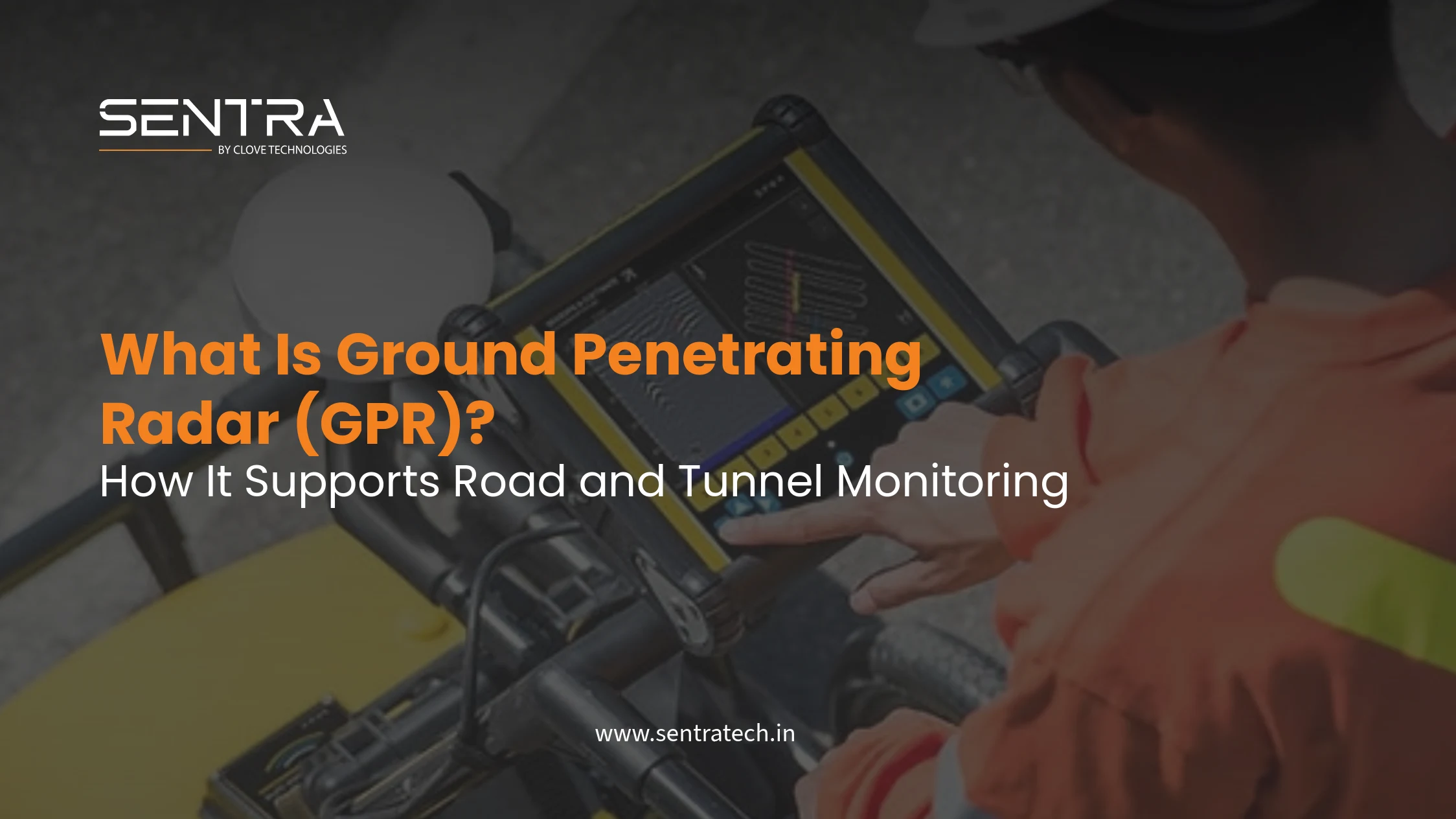
Ground penetrating radar (GPR) is a non-destructive testing (NDT) technique that sends short electromagnetic pulses into soil, pavement, concrete or rock and records the returning reflections. When a pulse crosses a boundary between materials with different electromagnetic properties, part of its energy is reflected back to the antenna. Moving the antenna along a measured line turns those echoes into a two-dimensional radargram; scanning a grid can produce a three-dimensional subsurface model.
How Ground Penetrating Radar Works
A GPR system contains a transmitter, a receiving antenna, timing electronics, odometry and a controller or survey computer. The transmitter radiates a broadband pulse, commonly from a shielded antenna mounted on a cart, vehicle or robotic platform. The receiver measures echo amplitude against two-way travel time. The result is not a photographic image: it is a time-domain measurement that must be interpreted using material properties, calibration and site context.
The most important parameter is relative dielectric permittivity
(εr). In a simplified non-magnetic medium, radar velocity is
approximately
v = c / √εr, where c is the speed of
light
in vacuum. A higher water content generally increases εr and slows the
wave. Metal, wet clay and saline groundwater also increase attenuation, which can make a
deeper reflector invisible even when the instrument is functioning correctly. Depth
estimates
therefore need calibration against known layer thicknesses, cores or trial pits.
Antenna Frequency, Resolution and Depth
GPR design is a compromise between penetration and resolution. Low-frequency antennas have longer wavelengths and usually reach greater depth, but small objects close together may merge into one response. High-frequency antennas resolve thin pavement layers, rebars and shallow cracks more clearly, but their energy is attenuated sooner. Typical engineering surveys may use approximately 100–250 MHz antennas for deeper soil or utility reconnaissance, 400–900 MHz for pavement and shallow utility work, and 1 GHz or higher for fine concrete inspection. These ranges are indicative, not guaranteed performance specifications; local conductivity controls the usable depth.
The vertical resolution is related to wavelength and pulse bandwidth, while the horizontal resolution depends on antenna footprint, survey speed, sampling interval and positioning accuracy. A useful survey records enough traces per wavelength and ties every trace to a reliable chainage or coordinate. Excessive vehicle speed, poor wheel odometry or irregular contact can create apparent discontinuities that are survey artefacts rather than defects.
What GPR Data Shows
Raw GPR data is commonly displayed as a radargram: distance along the survey line on the horizontal axis and two-way travel time, or an estimated depth, on the vertical axis. Continuous flat or gently curved bands can indicate layer interfaces. A point target such as a pipe, bar or cable often forms a hyperbola because the antenna approaches and then passes the object. Voids, disturbed fill and moisture changes may appear as disrupted horizons, amplitude changes or zones of signal loss rather than as a single clearly outlined shape.
Processing can include time-zero correction, dewow filtering, background removal, gain control, band-pass filtering, migration and topographic correction. Migration collapses the limbs of a hyperbola toward the likely target position, but it should use a defensible velocity model. Aggressive gain or filtering can make weak features look significant, so processed interpretations should always be reviewed alongside minimally processed data and field photographs.
GPR for Roads and Pavement Monitoring
For roads, GPR provides continuous coverage between isolated cores and visual inspections. A survey can map layer interfaces and identify locations where thickness, compaction or moisture differs from the surrounding pavement. It can also support utility mapping before milling, coring or excavation. When combined with GPS or distance-based chainage, the radar interpretation becomes a condition map that directs destructive verification to the most informative locations.
- Pavement layer thickness: estimate asphalt, base and sub-base boundaries after calibrating radar velocity against cores or known construction records.
- Voids and loss of support: identify anomalous zones beneath slabs, bridge approaches and utility trenches for targeted verification.
- Rebar, ducts and utilities: locate embedded or buried linear features before cutting, drilling, resurfacing or drainage work.
- Moisture and drainage: trace persistent high-attenuation or reflective zones that may indicate water ingress, poor drainage or saturated subgrade.
- Concrete and asphalt defects: investigate delamination, debonding, cracking and construction interfaces when the defect produces a detectable dielectric contrast.
GPR is particularly useful when the engineering question is spatial: where does the problem start, how far does it extend, and which locations deserve coring? It does not directly measure bearing capacity or guarantee that every crack is visible. Defect classification should be supported by cores, falling weight deflectometer results, visual condition surveys, drainage records and material data.
GPR for Tunnels and Underground Structures
In tunnels, GPR can be used on the crown, walls, invert, portals and approach slabs to investigate lining thickness, reinforcement cover, construction joints, voids behind the lining, water pathways and zones of debonding. A controlled scan along chainage provides a repeatable baseline for maintenance teams, especially where visual inspection is limited by lighting, traffic possessions or the presence of finishes.
Tunnel interpretation needs special care. Curved geometry, rough surfaces, wet concrete, mesh reinforcement and multiple reflections can complicate the radargram. Survey lines should be planned relative to the tunnel axis and structural grid, with clear chainage and orientation metadata. A suspected void behind a lining should be checked using a complementary method such as impact echo, ultrasonic testing, endoscopy through a carefully selected access point or a targeted opening. GPR identifies anomalies; it does not by itself prove the void volume or structural consequence.

A Defensible GPR Survey Workflow
- Define the decision: write down whether the survey is for utility avoidance, thickness mapping, defect screening, void investigation or a baseline condition record.
- Review the asset: collect drawings, geology, pavement build-up, drainage information, known services and access constraints. Mark exclusion zones and safe survey routes.
- Select frequency and geometry: choose antenna frequency, line spacing, orientation, scan rate and positioning method based on the target size and expected depth.
- Calibrate and collect: establish time zero, odometry and a site-specific velocity estimate. Record weather, surface condition, antenna setup, chainage and any interruptions.
- Process and interpret: retain the raw data, apply documented processing, pick reflectors and classify anomalies with confidence levels rather than presenting every response as a defect.
- Verify and report: compare interpretations with cores, trial pits, utility records, photographs or another NDT method. Deliver radargrams, plan locations, coordinates or chainages, depth assumptions and limitations.
Limitations and Common Interpretation Errors
GPR is not a universal subsurface camera. Conductive clay, saline soil, reinforced concrete congestion and wet conditions can attenuate the signal. A buried object with little dielectric contrast may be difficult to separate from its surroundings. Closely spaced utilities can overlap, oblique targets can be mislocated, and a depth estimate based on an incorrect velocity can be systematically wrong. Surface roughness, poor coupling, electromagnetic interference and unrecorded changes in survey speed can also reduce confidence.
The strongest practice is to state what the data supports and what it does not. Use GPR to reduce uncertainty and target verification, then combine it with advanced NDT, geotechnical investigation and structural health monitoring. For assets that need change detection after the survey, permanent sensors such as tiltmeters, vibration meters, crack meters or water-level instruments provide the time-series layer that a mobile GPR scan cannot.
How GPR Fits an Infrastructure Monitoring Program
GPR is most valuable as part of a monitoring decision chain. An initial scan establishes hidden geometry and condition; targeted verification confirms the mechanism; continuous sensors measure whether the condition is changing; and a dashboard or alert workflow connects the data to inspection and maintenance actions. For example, GPR may locate a weak or voided zone beneath a road, while vibration and tilt sensors track the response of the pavement, retaining structure or tunnel lining during construction and service.
Takeaway
GPR gives infrastructure teams a continuous spatial view of hidden conditions without excavation. Its findings become much more valuable when calibrated, verified with targeted investigation, and connected to continuous sensors that show whether a road, tunnel or underground structure is changing over time.
Explore Advanced NDT ServicesFrequently Asked Questions
GPR transmits short electromagnetic pulses into the ground and records echoes produced when the signal encounters a boundary with a different dielectric permittivity or electrical conductivity. Travel time and signal amplitude are processed into a cross-sectional radargram.
Depending on soil, moisture and frequency, GPR can help map pavement layer thickness, cracks and voids, rebar, ducts, buried utilities, sinkhole-related anomalies, moisture zones and areas of delamination or poor compaction.
There is no single depth for GPR. Low-frequency antennas can investigate deeper but with lower resolution, while high-frequency antennas provide finer detail at shallower depth. Conductive clay, saline water and reinforced concrete can significantly reduce penetration.
GPR reduces unnecessary excavation and improves targeting, but it does not eliminate the need for verification. It is also a survey method rather than a permanent time-series sensor, so it should be combined with boreholes, trial pits and continuous sensors when change over time matters.