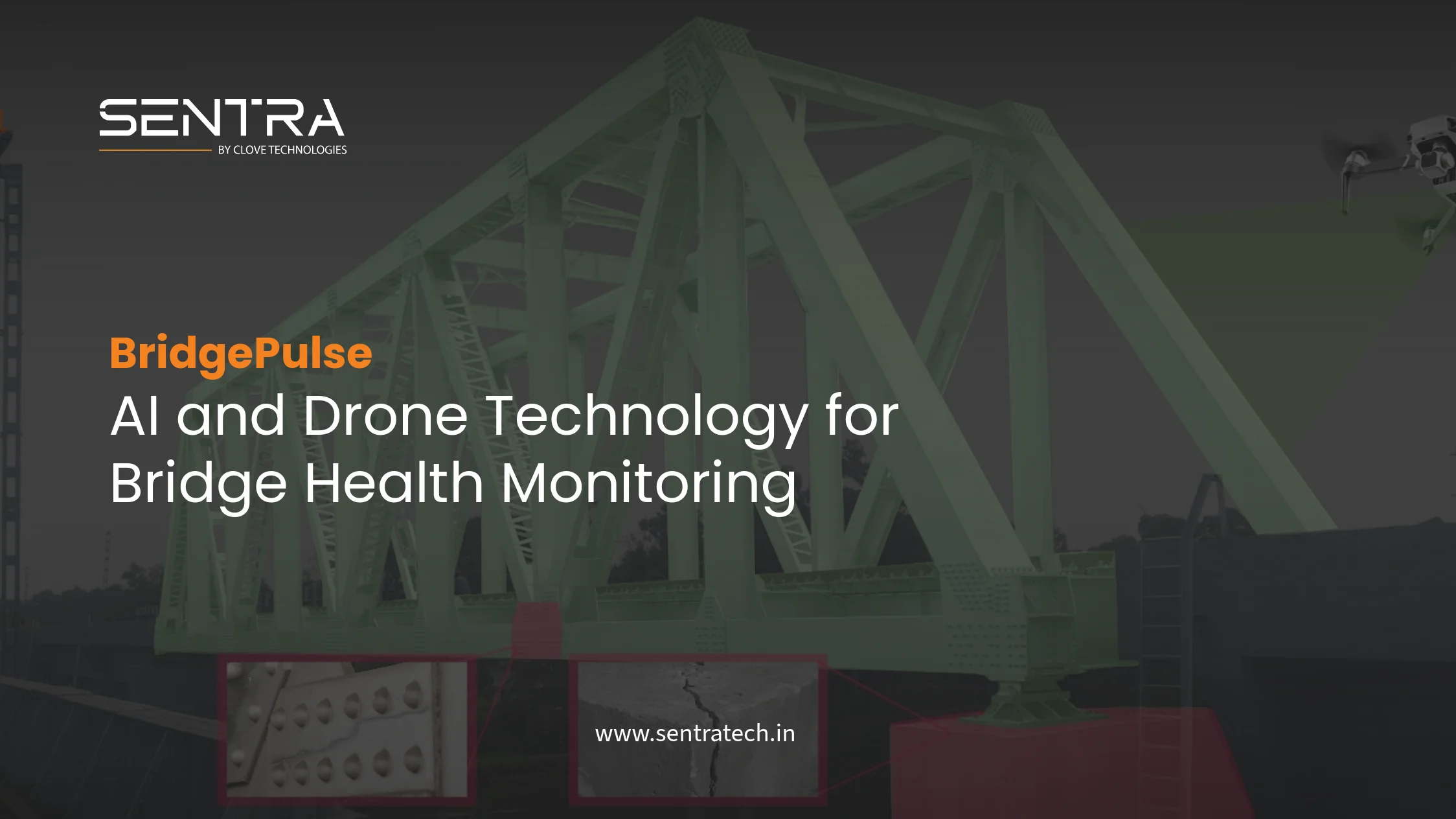
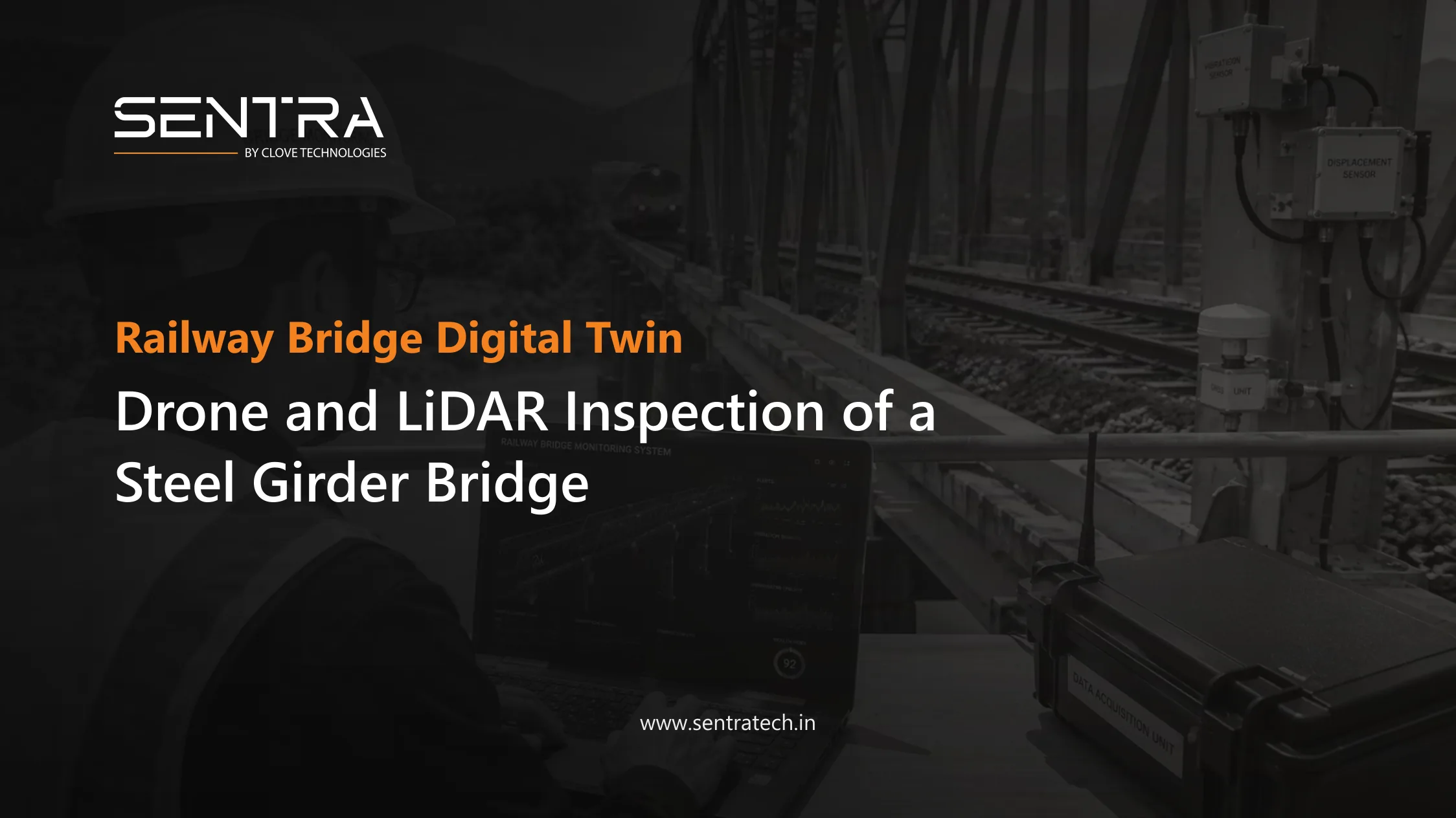
Bridge No. 60 DN carries the GDV-BVRT line over a single 40.23 metre steel open web girder span. It sits in the Vijayawada Division of South Central Railway, on the BZA-VSKP route, under the jurisdiction of Sr. DEN/Bridge Lines/BZA. What South Central Railway wanted from this bridge was not another inspection report. They wanted a measured three dimensional record of the structure as it stands today.
Clove Technologies delivered that record as a digital twin. The span was captured twice over, once from the air with a drone and once from the ground with a terrestrial LiDAR scanner, and the two datasets were registered into a single point cloud that became the geometric basis for the model. The whole job, from first site visit to handover, ran 60 days.
Project Details
| Parameter | Detail |
|---|---|
Client / authority | South Central Railway, Vijayawada Division |
Division | Vijayawada (BZA) |
Bridge | Br. No. 60 DN |
Bridge type | Steel open web girder (OWG) |
Span | 1 × 40.23 m |
Railway section | GDV-BVRT |
Main section | BZA-VSKP |
Jurisdiction | Sr. DEN/Bridge Lines/BZA |
Inspection technologies | Drone and terrestrial LiDAR |
Digital deliverable | Digital twin / digital model |
Execution period | 60 days |
Maintenance period | Nil |
Why This Bridge Was Hard to Document
An open web girder span is a lattice. Top and bottom chords, diagonals, verticals, cross girders, stringers, gusset plates and several hundred riveted connections, all of them structurally relevant and most of them out of arm's reach. Recording that by hand means rope access or a working platform, a possession window, and an engineer with a notebook working member by member.
Four constraints shaped how we approached the survey:
- Members high in the truss and beneath the deck are difficult to reach and riskier still to measure by hand.
- Manual measurement produces dimensions in a report. It does not produce geometry that anyone can open and interrogate later.
- Any activity beside a running line has to fit around train movements, which limits how long a team can stay on the structure.
- Inspection paperwork does not carry forward well. The next engineer inherits a description of the bridge rather than the bridge itself.
Reality capture answers all four. A scanner records the truss faster than a person can measure it, from positions that are safe to occupy, and what it produces is a coordinate record that stays useful long after the crew has left site.
How the Bridge Was Captured
01. Site reconnaissance and survey planningBefore any equipment came out, the team walked the site and worked out where a scanner could stand and what each position would see. Approach embankments, bank slopes, track alignment and clearance to the running line all decide scan station placement on a railway bridge. Traffic patterns decided the working windows. The output of this stage was a scan plan: station positions, overlap between them, and the drone flight lines needed to fill in what the ground stations would miss.
02. Drone data captureThe drone covered the parts of the bridge that a tripod cannot see. Top chord members, the upper bracing, the deck as a whole, the approaches and the ground around the abutments were photographed from the air. This is the same reasoning behind drone based bridge inspection and condition assessment: put the camera where the inspector would otherwise need scaffolding, and get the elevation views without closing the line.
Aerial imagery also gives context that a close range scan loses. Seeing the span in its setting, with the track running in and out of it, matters when you are later trying to interpret a detail in the model.
03. Terrestrial LiDAR scanningTerrestrial LiDAR did the geometric work. From each planned station the scanner recorded millions of range measurements, building a dense point cloud of the steelwork, the deck and the immediate surroundings. On an open web girder this captures the main girders, cross girders, bracing members, connection detail, bearings, deck geometry and the track, along with the true relative position of every one of those elements.
That last point is what separates a scan from a set of measurements. A LiDAR bridge inspection does not just tell you how long a member is. It tells you where that member sits in relation to every other member, which is the information a model needs and the information a tape measure cannot produce. Sentra supplies the laser scanners used for this class of work, including handheld SLAM units such as the Lixel K2 and the Lixel L2 Pro.
04. Point cloud processing and modellingBack in the office, the individual scans were registered into one coordinate system and merged with the drone data. Noise, vegetation and passing objects were cleaned out, and the cloud was cut into the sections an engineer would actually want to look at. LixelStudio handles registration and slicing for this kind of dataset.
Modelling then turned the cleaned cloud into structured geometry. This is the step that converts a mass of points into named components, and it is the core of digital engineering and documentation work: a scan on its own is a photograph in three dimensions, while a model is something you can query.
05. Digital twin deliveryThe finished deliverable is a digital twin of Bridge No. 60 DN. Engineers can rotate the span, section it, measure between any two points and inspect connections without going back to site. More importantly, the model gives inspection records, defect notes and maintenance history somewhere concrete to attach themselves, which is the point at which a 3D model stops being a drawing and starts being an asset register.
Technology Used
| Technology | Role on this project |
|---|---|
Drone survey |
Aerial coverage of top chords, deck and approaches, plus visual documentation of areas that are unsafe to reach on foot |
Terrestrial LiDAR |
High density 3D capture of the truss, bearings, deck and track geometry |
Point cloud processing |
Registration of scan stations, noise removal and organisation of the merged dataset |
Digital twin and BIM modelling |
Conversion of reality capture data into a structured, component level model of the bridge |
Sentra platform |
The environment that field data, sensor readings and inspection records are brought into around the model |
From Steel Span to Digital Asset
The pipeline on this project ran in one direction, each stage feeding the next:
Physical bridge → drone and terrestrial LiDAR capture → registered 3D point cloud → digital modelling → digital twin → ongoing inspection and asset management.
The last arrow is the one that matters commercially. Everything before it is a survey. What makes it a digital twin rather than a very good scan is that the model keeps accepting new information after handover. If you want the longer technical argument about mesh, point cloud and splat representations, we covered it in this comparison of digital twin formats.
What a Digital Twin Changes for Railway Bridges
A railway bridge is not a fixed object. Its condition changes, its inspection record grows, and the traffic it carries gets heavier over the decades. A digital twin gives all of that somewhere to live.
Engineers can see the structureA 3D model of the span is easier to reason about than an elevation drawing and a folder of photographs, particularly for anyone who has not personally stood on the bridge.
The existing condition is on recordReality capture fixes the geometry of the bridge at a known date. Any future scan can be compared against it, which turns "has this member moved?" into a measurable question.
Inspections can be planned against the modelAccess routes, sightlines and member locations can be worked out in the model before a team is mobilised, which shortens the time actually spent on the structure.
Records attach to componentsDefect observations, repair history and condition ratings can be linked to the specific gusset plate or diagonal they refer to rather than to a page number.
Measurements do not have to be repeatedOnce the geometry exists and is trusted, subsequent engineering work draws from the model instead of sending another crew out with a total station.
Adding Sensors to the Twin
A digital twin becomes considerably more useful once it is fed by something other than periodic surveys. The model is the visual layer; the interesting part is what you connect to it.
For a railway bridge that means bringing together inspection findings, the LiDAR and drone datasets, historical records and live sensor output in one place. Structural health monitoring instrumentation on the span reports strain, tilt, vibration and displacement continuously, and those readings mean more when they are tied to the member they came from. Longer term, that same stress history feeds fatigue and residual life assessment for the steelwork.
That is the route from periodic inspection to something closer to continuous condition awareness, and it is the approach we took on a comparable structure in our IoT bridge monitoring case study. Both projects sit within Sentra's wider work on railway infrastructure monitoring.
What the Project Delivered
South Central Railway now holds a measured digital record of Bridge No. 60 DN that did not exist before. Concretely, the deliverable supports:
- Existing condition documentation of the span at a known date
- 3D visualisation of the truss, deck, bearings and track geometry
- A spatial reference for planning future inspections
- Engineering assessment and rehabilitation design work
- Maintenance planning against actual geometry rather than as built drawings
- A structure to hang future sensor data and inspection records on
All of it produced in 60 days, with no maintenance period attached to the contract, and without the extended possessions that a manual survey of a 40 m truss would have required.
Conclusion
Bridge No. 60 DN is a straightforward demonstration of what reality capture does for railway assets. Drone imagery and terrestrial LiDAR between them recorded a 40.23 metre open web girder span in detail, and the resulting point cloud was turned into a digital twin that South Central Railway can keep using long after the survey crew went home.
The model on its own is documentation. Connected to asset monitoring and management and to sensors on the structure, it becomes the place where a bridge's condition is actually tracked over its remaining life.
Need a digital twin of your bridge?
Tell us about the structure and we will scope the drone and LiDAR survey, the modelling, and what it would take to connect monitoring to it.
Contact us